victron battery shunt wiring diagram – victron bmv 700
BATTERY ONLY side of the shunt Victron GX product range https://ve3nl/ VictronConnect-manual VictronConnect manual Loads & Chargers Start or second battery Loads & Chargers Loads & Chargers Loads & Chargers Loads & Chargers, Author: Margreet Leeftink Created Date: 7/21/2020 11:24:24 AM
victron battery shunt wiring diagram
· Buy it here affiliate links: 500A: https://lddy,no/to0k1000A: https://lddy,no/to0nAmazon smartshunt listing: https://amzn,to/35toVEDFavorite crimper: htt
Auteur : DIY Solar Power with Will Prowse
Shunt install question bmv 702 the t80 wiring diagram 31 to battery bank boat smartshunt vehicle chassis grounding monitor best red rover trimetric installation installing a marine how in adding bus bar for negative terminals , Shunt Install Question Bmv 702 Victron Community The T80 Shunt Wiring Diagram 31 Scientific The T80 Shunt Wiring Diagram 31 Scientific Wiring Shunt To Battery Bank Boat
Victron DIY Installation Manual
· Fichier PDF
shunt wiring diagram
Installing A Battery Monitor
The board offers easy integration of a Victron Battery Voltage Monitor BMV, battery charger and a DC/AC battery inverter 300w @ 12v, 700W @ 24V, The distribution Board comes Prewired with a 10 amp cigarette lighter socket, 2 x USB ports 2,1 mm DC socket for lights and 40 amp Anderson Plug for Inverter, Safety The RPC Victron MPPT Distribution board is an electrical device with potentially
Help with install of Victron Energy Battery Monitor BMV
Wiring Unlimited – Rev 06 7 Each material has its own specific resistance, It is measured in Ω,m, and the symbol is ρ rho, The table on the right lists various conducting materials, their electrical conductivity
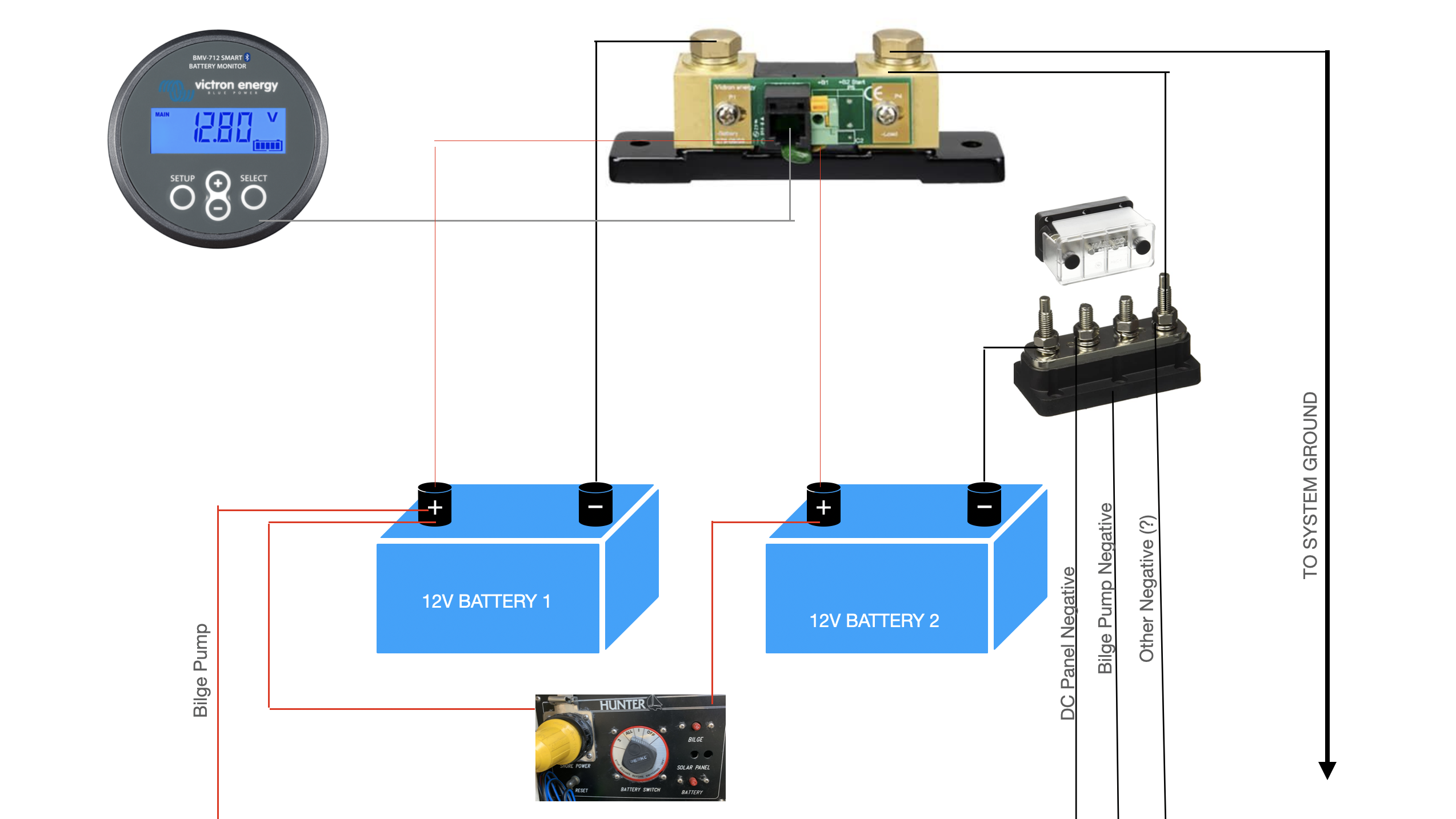
· Confused about how to wire a Victron 702 on a boat – here is wiring diagram along with pictures of batteries Part of confusion is that I have an extra wire from starter battery into panelwiring diagram attached along with pictures of batteries and a batter switch 1 house, 2 start or both that I …
| Victron Smart Shunt not showing charging current | 30/03/2021 |
| wiring – Victron Community | 22/11/2020 |
| wiring diagram – Victron Community |
Afficher plus de résultats
BMV 712 Smart Quick installation guide Battery safety warnings
· Fichier PDF
Shunt install question bmv 702 the t80 wiring diagram 31 to battery bank boat red rover trimetric installation monitor best installing a marine mini circuit breaker qo 90a 712 location and for how in Shunt Install Question Bmv 702 Victron Community The T80 Shunt Wiring Diagram 31 Scientific Wiring Shunt To Battery Bank […]
System schematics
9,1 Battery bank and midpoint wiring diagrams ,,28 9,1,1 Connecting and monitoring midpoint in a 24V battery bank ,,28 9,1,2 Connecting and monitoring midpoint in a 48V battery bank ,,29 9,2 Midpoint deviation calculation ,,29 9,3 Setting the alarm level,, 30 9,4 Alarm delay,,30 9,5 What to do in case of an alarm during charging,,30 9,6 What to do in case of an alarm
INSTALLATION GUIDE
· Fichier PDF
· I purchased the Victron Smart Shunt and I’m not entirely certain how to correctly wire the Smart Shunt in this scenario, I have a 100w Renogy kit with the 30A Wanderer controller, a battery, and an inverter, I have included a diagram of what I *thought should be correct, however I read this in the Smart Shunt manual; “there should be no other connections on the battery negative” If that is the
Wiring diagram for a VE,Bus panel; AC + DC System for vehicles; VE,Bus BMS example with 3kW 12V MultiPlus 230V ; AT-1 split phase 240V to 120-240V with Quattro 240V; AT-2 step up 120 to 240V with Quattro 120V; AT-3 split phase 120V to 120-240V with Quattro 120V; AT-4 stacked inverter 2x120V to 120-240V with 2xQuattro 120V; AT-5 split phase 240V to 120-240V with Generator 240V; Blue Power
How would I wire a Victron 702 battery monitor with this
Battery Monitor Diagram, This article features the older Victron BMV-602, The 602 has been replaced by the BMV-7oo series, Everything in this article is still relevant to the current series of BMV monitors, Please support MarineHowTo,com by purchasing your Victron battery monitor through us! This web site cannot remain free without your support! MarineHowTo,com – Shop Victron Products
The thick lines in the wiring diagram represent the main current path cables, These cables must be of a heavy duty type and able to carry full load current drawn from the battery, The five wires going to the battery monitor unit can be connected to shunt and battery using universal crimp terminals, When routing the cable from monitor to battery system, avoid running it with mains cables over
shunt wiring diagram
Victron Smart Shunt – “correct” installation
Wiring Unlimited
· Fichier PDF
· Please find a summary of the current set-up and wiring diagram work in progress below – thank you for your help! – The Varta house batteries are wired in parallel I have also included the connection to the start battery also Numax 12v 70ah – There are two separate shunts fitted to one of the Vartas batteries and one to the Numax I believe these are connected to the Sterling Battery
Manual
· Fichier PDF
Victron Energy 500A Smart Shunt Beginner Friendly